FXL DATA
Drag Racing Data Loggers
FXL32 Superceded by the FXL35 (24 July 2006)
This model is obsolete. Retro circuit boards have been developed

The FXL32 is a 32 Channel Data Logger designed specifically for V8 engines used in Group 2 drag racing. This is a well developed, proven, mature product, derived from the highly successful FXL25. The logger monitors up to 4 switching inputs standard and up to four rpm's standard. Optional sensors are required if the vehicle uses a magneto or a manual transmission. It also monitors up to eight exhaust gas temperatures standard, battery volts standard and up to four optional pressures and one optional G Meter. There are two inputs for oxygen sensing. (Customer to supply the oxygen sensors). There are 6 unused 0 to 5 volt analog inputs available for future use.
It can log:
Four switch positions:
Wide Open Throttle - Standard. This triggers the recording.
Two Step or Transbrake - Standard. Voltage seeking. This is the primary Record Inhibit line.
Two Step - Earth seeking, like the old Dyna ignitions and new MSD ignitions. This is the secondary Record Inhibit line.
Shift Light - Standard, but only for 12 volt bulb shift lights. Records when the shift light is on. May not work with LED shiftlights.
Four rpm's:
Engine RPM from the tacho terminal of an MSD ignition - Standard.
Transmission Input Shaft RPM - Optional for Manual Transmissions.
Drive Shaft RPM - Sensor and collar supplied standard.
Right Hand Front Wheel Speed in MPH - Sensor and 5 magnets standard.
Magneto equipped engines usually need the optional crank pickup and magnet kit.
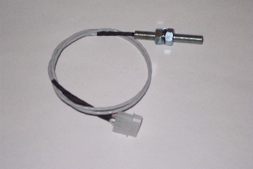

RPM pickup and untrimmed four magnet collar.
Eight K type thermocouples are supplied with the kit. The thermocouples are a short probe 110 mm ( approx 4.5 inches ) long. Each thermocouple requires a braided cable. The standard length is 2 meters. Any extra length is charged out at $8.00 per meter. (2006 price)

Battery Volts Monitor is standard. This is from a single external cable which is connected to any point the customer wants to monitor, typically the voltage applied to the ignition.
Pressures: Up to four optional pressure sensors can be added. The customer may choose from a combination of up to four high quality, high accuracy stainless steel pressure senders or up to four VDO Marine two wire 10 - 180 ohm oil pressure senders, or any combination of the two types. These VDO senders are not calibrated to readout on the graph, however they give an excellent indication of pressure. The cost per VDO sender is $X or $X.00 which includes the cable and is considerably less than the stainless steel senders. These senders are an oil pressure sender, and were never designed to handle methanol fuel. The preferred setup for the pressure senders is two high accuracy stainless steel senders to monitor fuel pressure and boost pressure, and two VDO oil pressure senders to monitor oil pressure and transmission oil pressure. This is an excellent setup for a supercharged fuel injected engine running an auto transmission.
Stainless Steel pressure senders: Obsolete.
0 - 200 psi Normally used for fuel injection pressure.
0 - 100 psi Normally used for boost pressure.
0 - 50 psi May be used for boost pressure or carby fuel pressure.
0 - 25 psi Absolute. This pressure sender monitors from total vacuum to 10 psi above atmospheric. It can be used for up to four separate functions, although not at the same time. It can be used to monitor scoop pressure, fuel pressure up to 10 psi, sump vacuum and plenum vacuum. If you run a normally aspirated engine, then this is the one pressure sender you should have, particularly to monitor scoop pressure. If the scoop can make 1 psi of pressure, then you will get 7 percent more power. Pro Stock cars can get this at 170 mph. This is why some cars can overhaul others at the top end.
VDO Oil Pressure senders: (Metric rating) DO NOT USE. NOT SUITABLE FOR DRAG RACING.

0 - 2 Bar (28 psi) Rarely used, not held in stock.
0 - 5 Bar (72 psi) Rarely used, not held in stock.
0 - 10 Bar (140 psi) Normally engine oil pressure.
0 - 25 Bar (360 psi) Normally auto trans oil pressure.
The VDO senders do not read out correctly on the graph. A conversion sheet to convert the binary number to pressure is supplied.
To find out what the pressure rating of the VDO sender is, look at the big nut at the threaded end. It will have a figure like 0 - 10 or 0 - 25, indicating 0 - 10 or 0 - 25 Bar. That is the metric pressure rating. 1 bar is approx 14.1 psi
You CANNOT use them to measure methanol fuel pressure.
Pressure senders are NOT covered by any form of warranty.
G Meter: An optional G Meter module can be fitted to the vehicle and wired into the Thermocouple Amplifier Module. The G Meter needs to be mounted to the chassis of the vehicle and must be pointed in the direction of travel. Arrows are written on the module to indicate the front of the vehicle. $X each.
Six unused analog inputs: This model has 6 of 0 - 5 volt industry standard analog inputs reserved for future use. They are pins 1 to 6 of the 15 pin connector at the top of the logger, beside the RPM and Switch loom. Pins 7 and 8 are unused, pins 9 to 14 are earths, and pin 15 is the +12 volt supply, less 0.7 volts because of the protection diode. The customer may use these inputs if they have the technical knowlege, but must be aware that exceeding the 0 - 5 volt standard may (will) destroy the microprocessor.
Cables: The system comes with a wiring harness cut to the customer requirements, 1.5 meter downloading cable to connect the logger to a lap top and DOS based software for downloading the data and viewing the graph. The customer is required to quote the cable lengths from a list. See the list in the Before You Buy page. There is an optional 10 meter long Downloading Cable if the customer will be keeping the computer in the trailer rather than having to mount the computer beside the logger for downloading. This cable is $X if purchased separately or an extra $X if selected as an option rather than the 1.5 meter Downloading Cable.
Sample Rate: Sample rate is 100 samples per second. Recording time is 17.00 seconds triggered from the Wide Open Throttle switch when the two step or transbrake is released. This lines up the start of the race with the Time Zero on the Graph. There is a small portion of the recording ( 1.6 seconds ) left behind the Time Zero, which means the total recording time is actually 18.60 seconds.
Prices: Price starts at $ (off market) and this is for a fully working system to suit a race car with an MSD electronic ignition and an auto trans.
This includes:
- 1 x FXL32a Data Logger with Serial Number quoted. Serial Number and Customer Number are the same.
- 2 x RPM Pickups. This is for the driveshaft rpm and front right hand wheel speed. These pickups are identical and can be swapped. 5 x 1/4 x 1/4 inch magnets are supplied for the front wheel.
- 1 aluminium collar with 4 magnets pressed into the outer rim. This has a hole (approx 25mm) in the center. The customer has to turn the centre in a lathe and press it to the yoke of the pinion of the diff)
- Locking on-off switch. This is the power switch and connects the battery to the logger.
- Wide Open Throttle switch. This is a simple micro switch that the customer fits under the accelerator pedal of the car.
- 8 x Exhaust Gas Temperature probes ( EGT ) Customer to quote what fittings to use, either 1/4 BSP 18 tpi recommended or 1/8 BSP 28 tpi.
- Loom cut to the customers requirements. The cable requirements are listed in the Before You Buy section.
- 1.5 meter downloading cable. This suits laptop computers. If you want to use a desktop computer in the trailer, it is highly recommended that you purchase the optional 10 meter cable for an extra $X. The customer must ensure that their computer has a 9 pin serial port (RS232C). The downloading cables are known as Null Modem cables.
- DOS based software is standard.
- Tax Invoice with price paid and amount of GST included in the price.
- Optional RPM Pickups and magnets to suit transmission input shafts are custom made and cost $x.
- Optional Stainless Steel Pressure Transducers are $x AUD each.
- Optional VDO Engine Oil pressure senders are $x AUD each.
- Optional VDO Transmission Oil Pressure senders are $x AUD each.
- Optional G Meter is $x AUD
- Freight is extra.
Technical Specifications: 24 July 2006
RPMs: Up to 4. Only Hall Effect Switches are used as these have a high immunity to RF interference. These Hall Effect Sensors are only triggered by the South end of a magnet. Engine rpm can also be monitored if the vehicle has an MSD or Dyna or similar ignition with a tacho terminal. The logger can pick up from the tacho terminal, saving the cost and difficulty of mounting a sensor and magnets to the crank. Input shaft rpm sensing can be done on a manual transmission. It is virtually impossible with an auto because the pump drive is in the way.
Switch Monitors: Up to 4. Wide Open Throttle is essential to trigger the recording. The others are two step or transbrake monitor which is used as 'Record Inhibit' so the vehicle can go to Wide Open Throttle on the line, but not trigger the recording. A +12 volt shift light can be monitored as can a spare input, usually for a nitrous solenoid. On the FXL22, this input is an earth seeking inhibit line to suit Dyna Ignition two steps.
Thermocouples: Up to 8 K Type ( Yellow Connectors ) isolated from earth. Only open tip thermocouples are used.
Pressure Senders: Up to 4. Usually a combination of up to two high accuracy stainless steel senders and up to two VDO Marine two wire 10 - 180 ohm senders are used for the FXL32. The FXL22 only supports the stainless steel senders.
Oxygen sensing: The FXL32 has two internal amplifiers that the customer may connect up to two oxygen sensors. Because the voltage from the oxy sensor is low, typically less than 1 volt, the logger has an amplifier to increase the voltage slightly. If the binary number produced by the logger is multiplied by 0.0069 then it will produce the original voltage made by the oxy sensor.
G Meter: Only one is needed. It is connected to the Thermocouple Amplifier Module.
Main module Connector pinouts.The FXL22, FXL25, FXL32 and FXL35 have one common connector which is where the RPM and Switch loom plugs in. This is a 25 pin ' D ' connector. Note that the FXL22 uses +5 Volts DC for its switches and rpm pickups and the FXL25, FXL32 and FXL35 use +9 Volts DC. The FXL32 and FXL35 are derived from the FXL25 and only one pin is different, that is Pin 10. On the FXL32 and FXL35 it was decided to make it an earth seeking record inhibit, the same as the FXL22, so it can accommodate early Dyna ignitions and late MSD ignitions which have earth seeking two steps.
The Four RPM cables will have heat shrink tubing for insulation and identification. The color corresponds to the color of the traces on the DOS based software.
- RPM 1 Engine RPM cable if fitted, will have Blue heat shrink.
- RPM 2 Input shaft RPM cable if fitted, will have Red heat shrink.
- RPM 3 Drive shaft RPM cable is always supplied as standard, will have Green heat shrink.
- RPM 4 Front Right Hand Wheel speed if fitted, will have Black heat shrink.
Pin Function: ( Viewed from behind the connector where all the wiring comes out )
- Pin 1 +12Volts main power - with short lengths of Red heat shrink.
- Pin 2 RPM 1 Signal - Engine rpm signal return. White/Blue wire.
- Pin 3 RPM 1 Power - Engine rpm sensor power. White/Orange wire.
- Pin 4 RPM 2 Signal - Input Shaft rpm signal return. White/Blue wire.
- Pin 5 RPM 2 Power - Input Shaft rpm sensor power. White/Orange wire.
- Pin 6 RPM 3 Signal - Drive Shaft rpm signal return. White/Blue wire.
- Pin 7 RPM 3 Power - Drive Shaft rpm sensor power. White/Orange wire.
- Pin 8 RPM 4 Signal - Front Right Hand Wheel speed signal return. White/Blue wire.
- Pin 9 RPM 4 Power - Front Right Hand Wheel speed sensor power. White/Orange wire.
- Pin 10 Dual purpose input. On the FXL25 it is a voltage seeking input usually used for monitoring when a Nitrous solenoid is switched on or off, and on the FXL22 and FXL32 it is an earth seeking input used as a record inhibit to suit Dyna ignitions, new style MSD ignitons or Junior dragsters using a switch on the brake pedal. Usually has short lengths of blue heat shrink tubing for identification purposes.
- Pin 11 Wide Open Throttle switch power. This is a White/Blue wire which goes to either contact on the Wide Open Throttle switch. There will always be a companion White wire inside the cable. This White wire is an earth from the logger. The shield is earthed at the logger end of the cable. It is NOT earthed at the switch. Wrap insulating tape or put on heat shrink tubing at the switch end.
- Pin 12 Two Step or Transbrake switch input. Single White wire with short lengths of Green heat shrink tubing. This is a voltage seeking input on all models.
- Pin 13 Shift Light +12 volts input. Single White wire with short lengths of red heat shrink tubing. DO NOT Confuse this wire with the main +12 Volts input.
- Pin 14 Master earth. Has short lengths of Black heat shrink tubing.
- Pin 15 Earth for RPM1 Sensor
- Pin 16 Earth for RPM1 Shield
- Pin 17 Earth for RPM2 Sensor
- Pin 18 Earth for RPM2 Shield
- Pin 19 Earth for RPM3 Sensor
- Pin 20 Earth for RPM3 Shield
- Pin 21 Earth for RPM4 Sensor
- Pin 22 Earth for RPM4 Shield
- Pin 23 Earth for Wide Open Throttle Switch
- Pin 24 Earth for Wide Open Throttle Switch shield
- Pin 25 MSD or Dyna Ignition tacho terminal take off. This will have short lengths of Blue heat shrink tubing. Not to be confused with the nitrous switch input on pin 10.
Thermocouple connector for the FXL25 and FXL32.
25 Pin D connector (not compatible with the FXL22 or the FXL35.)
Top Row
- Pin 1 is Cylinder 1 positive input YELLOW, matches pin 14.
- Pin 2 is Cylinder 2 positive input YELLOW, matches pin 15.
- Pin 3 is Cylinder 3 positive input YELLOW, matches pin 16.
- Pin 4 is Cylinder 4 positive input YELLOW, matches pin 17.
- Pin 5 is Cylinder 5 positive input YELLOW, matches pin 18.
- Pin 6 is Cylinder 6 positive input YELLOW, matches pin 19.
- Pin 7 is Cylinder 7 positive input YELLOW, matches pin 20.
- Pin 8 is Cylinder 8 positive input YELLOW, matches pin 21.
- Pin 9 is an earth.
- Pin 10 is G Meter signal, 0 to +5 volts only.
- Pin 11 is G Meter power, nominally +9vdc.
- Pin 12 is spare 0 to +5 volts only on FXL25, buffered input on FXL32 for oxy sensors.
- Pin 13 is spare 0 to +5 volts only on FXL25, buffered input on FXL32 for oxy sensors.
Bottom Row
- Pin 14 is Cylinder 1 negative input RED, matches pin 1.
- Pin 15 is Cylinder 2 negative input RED, matches pin 2.
- Pin 16 is Cylinder 3 negative input RED, matches pin 3.
- Pin 17 is Cylinder 4 negative input RED, matches pin 4.
- Pin 18 is Cylinder 5 negative input RED, matches pin 5.
- Pin 19 is Cylinder 6 negative input RED, matches pin 6.
- Pin 20 is Cylinder 7 negative input RED, matches pin 7.
- Pin 21 is Cylinder 8 negative input RED, matches pin 8.
- Pin 22 is earth for the thermocouple loom, not always used.
- Pin 23 is earth for the G Meter. Interchangeable with Pin 24.
- Pin 24 is earth for the shield of the G Meter cable. Interchangeable with Pin 23.
- Pin 25 is battery volts monitor. 0 to +25vdc only.
FXL32 Pressure Connector Pinouts:
This is a 15 pin Dee connector. This connector has had many variations in pinouts. The most common are:
- Pin 1 Analog 1 0 to +5vdc normally used for a stainless steel fuel pressure input. 1 kohm input resistance.
- Pin 2 Analog 1 sensor power. Some have +9vdc, some have the logger supply less 0.7 vdc, some have earth.
- Pin 3 Analog 2 0 to +5vdc normally used for a stainless steel boost pressure input. 1 kohm input resistance.
- Pin 4 Analog 2 sensor power. Some have +9vdc, some have the logger supply less 0.7 vdc, some have earth.
- Pin 5 Analog 3 0 to +5vdc normally used for a VDO engine oil pressure input. Normally is +5vdc if the channel is configured for the VDO sender.
- Pin 6 Analog 3 sensor power. Some have +9vdc, some have the logger supply less 0.7 vdc, some have earth. Not used if a VDO sensor is used.
- Pin 7 Analog 4 0 to +5vdc normally used for a VDO transmission oil pressure input. Normally is +5vdc if the channel is configured for the VDO sender.
- Pin 8 Analog 4 sensor power. Some have +9vdc, some have the logger supply less 0.7 vdc, some have earth. Not used if a VDO sender is used.
- Pin 9 to 14 are earths.
- Pin 15 is almost always either +9vdc or supply volts less 0.8vdc. Later models are going to be earth, because the power for the sensors comes from pins 2, 4, 6 or 8.
FXL32 Spare Connector Pinouts:
The FXL32 has a "Spare" connector. This is a 15 pin Dee connector that has 6 analog inputs plus several earths and a supply voltage pin.
Be very aware that pins 1 - 4 connect directly to the microprocessor. If you exceed 5 volts, or present a negative voltage to any of these pins, then you WILL DESTROY the microprocessor.
Top Row
- Pin 1 Analog (0 - +5v input, 1 kohm, 2u2) Spare
- Pin 2 Analog (0 - +5v input, 1 kohm, 2u2) Spare
- Pin 3 Analog (0 - +5v input, 1 kohm, 2u2) Spare
- Pin 4 Analog (0 - +5v input, 1 kohm, 2u2) Spare
- Pin 5 Analog (0 - +5v input, 1 kohm, 2u2) Spare
- Pin 6 Analog (0 - +5v input, 1 kohm, 2u2) Spare
- Pin 7 Not Used
- Pin 8 Not Used
Bottom Row
- Pin 9 Earth
- Pin 10 Earth
- Pin 11 Earth
- Pin 12 Earth
- Pin 13 Earth
- Pin 14 Earth
- Pin 15 is supply voltage less approximately 0.8 volt from the reverse polarity protection diode.
Click on BACK to Return